Identification of Noise Sources During Launch Using Phased Array Microphone Systems
Identification of Noise Sources During Launch Using Phased Array Microphone Systems Every part of a launch vehicle, launch pad, and ground operation equipment is subjected to the high acoustic load generated during lift-off [1]. Therefore, many extreme measures are taken to try to suppress this acoustic environment by damping with a water deluge system and […]
Identification of Noise Sources During Launch Using Phased Array Microphone Systems
Every part of a launch vehicle, launch pad, and ground operation equipment is subjected to the high acoustic load generated during lift-off [1]. Therefore, many extreme measures are taken to try to suppress this acoustic environment by damping with a water deluge system and diverting engine plumes away from the vehicle via flame trenches. Even single decibel reductions of the acoustic levels can translate into a sizable reduction of acoustic loadings, certification needs, operational costs, and even vehicle weight. Therefore, lowering the acoustic level via various mitigation schemes is an important aspect of a launch pad design.
In 2011 and 2012, the NESC sponsored research into the effectiveness of a microphone phased array (MPA) to identify noise sources and tested the array during an Antares launch from the Wallops Flight Facility [2]. This simple prototype array was able to identify impingement-related noise sources during the launch.
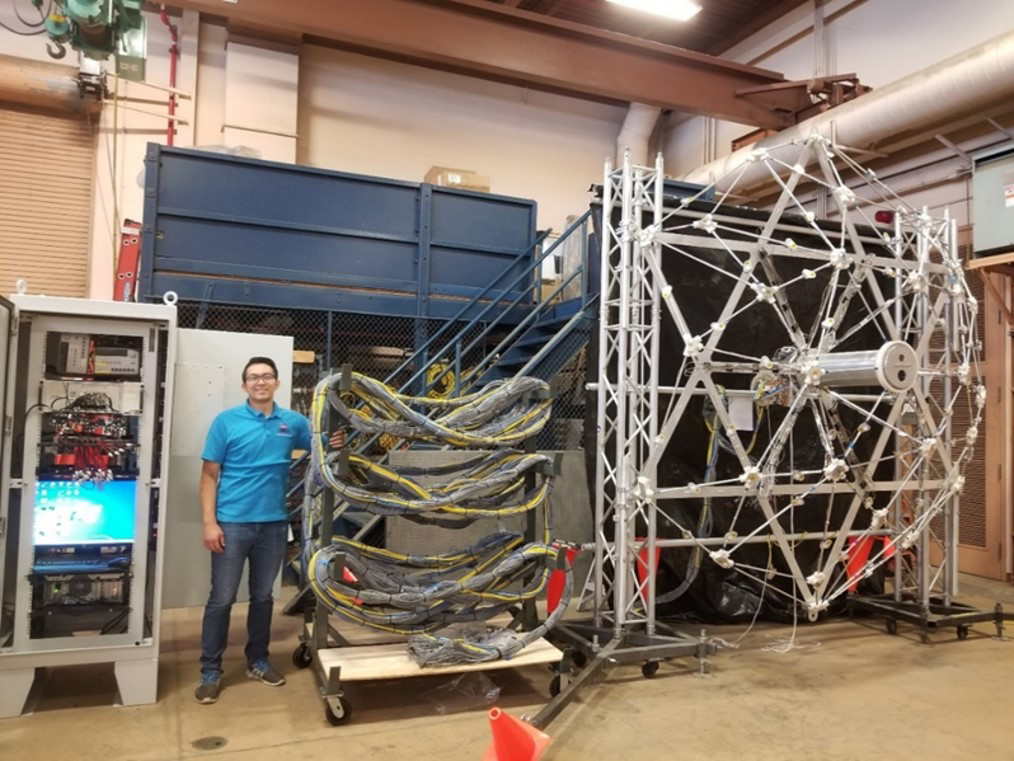
Today, building on this previous work, a new open-space truss MPA architecture is in development and test for use during the Artemis II launch. This truss structure consists of an aluminum tubular frame holding 70 microphones mounted in optimized positions over a dome-shaped surface (Figure 1). The center canister structure holds visible and infrared cameras as well as the amplifier electronics that transfer and relay microphone signals out to data cables that send information to the ground-mounted data acquisition system. The collected data are postprocessed using a functional-orthogonal beamforming routine that minimizes the effects of side lobes and reflections on the acoustic signal [3]. This produces a much cleaner image of primary noise impingement sources emanating from the vehicle and launch pad structures.
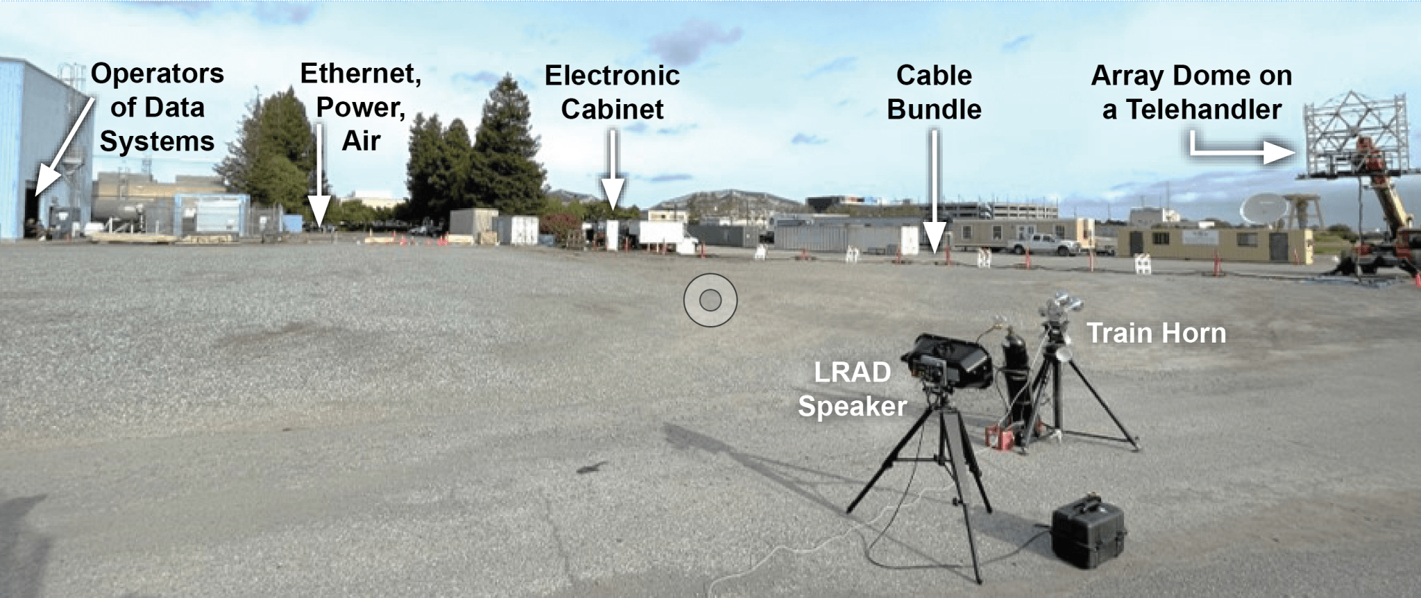
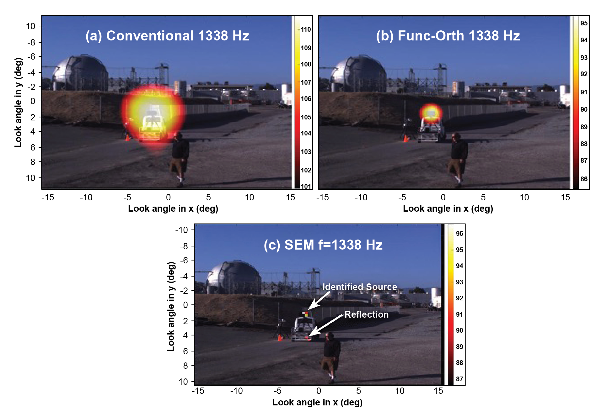
The NESC activity is performing verification and validation tests to determine the MPA’s environmental survivability and validate the beamforming capability. This is being done using a phased testing approach. Phase 1 testing performed at ARC elevated the MPA (Figure 2) and used horns and speakers of known intensity to ensure its ability to identify and separate noise sources (Figure 3).
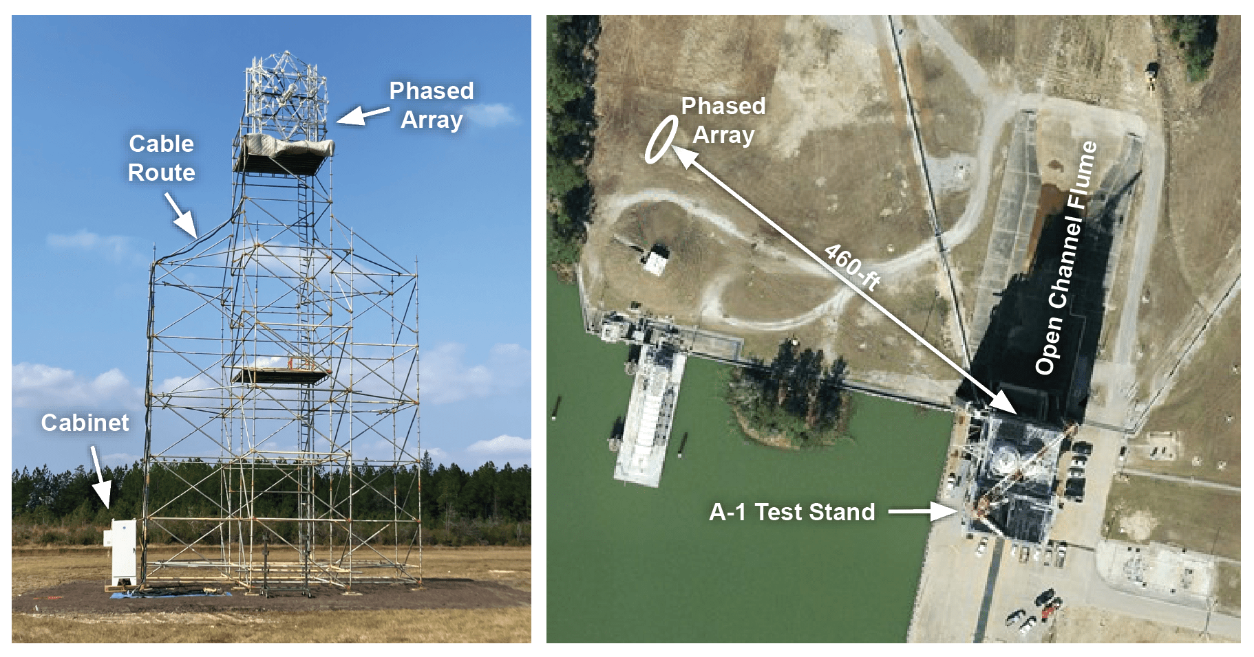
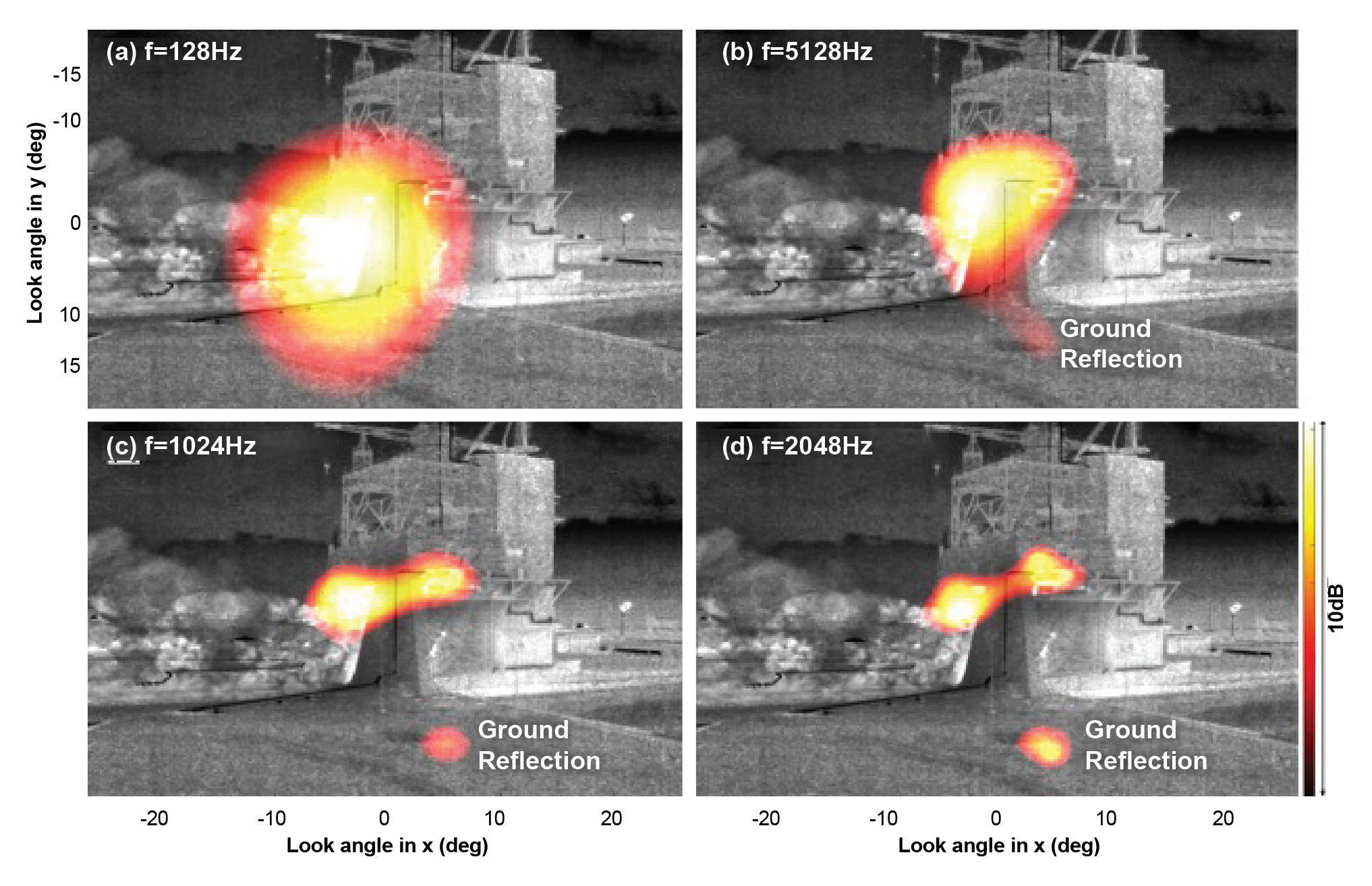
In phase 2, the system was subjected to an actual engine noise environment during a static fire test at SSC. The MPA viewed the A-1 engine test stand during an RS-25 engine test from 460 feet, a similar distance from KSC Pad 39B to the lightning tower, where the MPA will be mounted for Artemis II (Figure 4). Results successfully identified and pinpointed the transient engine acoustic sources during the test (Figure 5).
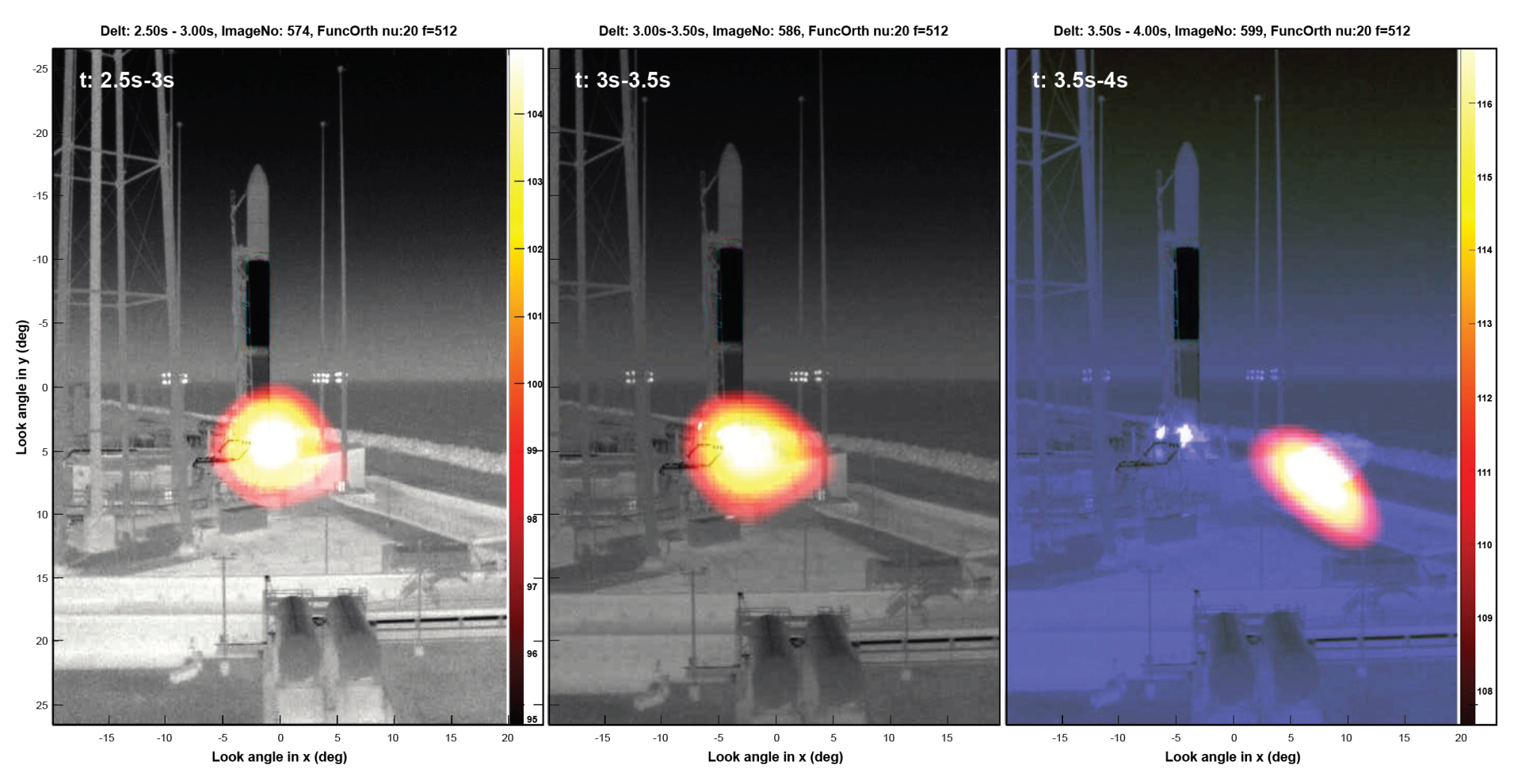
The final test occurred during the NG-19 Antares launch from the Wallops Flight Facility in July 2023. The MPA tracked the plume and acoustic environment during the launch, showing transition from initial engine thrust to the overpressure environment flowing from the flame trench as the vehicle lifted off (Figure 6). The array was able to collect meaningful data while mounted outside, under acoustic conditions similar to those expected during the Artemis II launch and also subjected to heat, humidity, salt air, and extreme weather.
Next, the MPA will be deployed at KSC for the Artemis II launch to measure the acoustic impingement and identify critical noise sources during that event. The data collected will help further refine and optimize the sound suppression systems for Artemis III and future launches.
References:
- Eldred, K. M. & Jones, G. W., Jr., “Acoustic load generated by the propulsion system,” NASA SP-8072, 1971.
- Panda, J., Mosher, R. N. & Porter, B. J., “Noise Source Identification During Rocket Engine Test Firings and a Rocket Launch,” Journal of Spacecraft and Rockets, Vol. 51, No. 4, July-Aug 2014. DOI: 10.2514/1.A32863
- Dougherty, R.P., “Functional Beamforming for Aeroacoustic Source Distributions,” 20th AIAA/CEAS Aeroacoustics Conference, 10.2514/6.2014-3066, 2014.
For more information, contact:
Dr. Jayanta Panda jayanta.panda-1@nasa.gov
Kenneth R. Hamm, Jr. kenneth.r.hamm@nasa.gov
Joel W. Sills joel.w.sills@nasa.gov
What's Your Reaction?





.jpg?#)


