Advancing Human Spaceflight Safety
As NASA continues to pursue new human missions to low Earth orbit, lunar orbit, the lunar surface, and on to Mars, the NESC continues to provide a robust technical resource to address critical challenges. The NESC Environmental Control and Life Support Systems (ECLSS), Crew Systems, and Extravehicular Activity (EVA) discipline is led by the NASA […]
As NASA continues to pursue new human missions to low Earth orbit, lunar orbit, the lunar surface, and on to Mars, the NESC continues to provide a robust technical resource to address critical challenges.
The NESC Environmental Control and Life Support Systems (ECLSS), Crew Systems, and Extravehicular Activity (EVA) discipline is led by the NASA Technical Fellow for ECLS, Dr. Morgan Abney, ECLSS & Crew Systems Deputy Dave Williams, Extravehicular & Human Surface Mobility Deputy Danielle Morris, and EVA Deputy Colin Campbell. In 2023, this team led assessments and provided support to the Commercial Crew Program, ISS, Orion Multi-Purpose Crew Vehicle, Extravehicular and Human Mobility Program, Gateway International Habitat, and Moon-to-Mars Program. Three of the most notable activities in 2023 are briefly described below.
Mitigation for Water in the Helmet During EVA
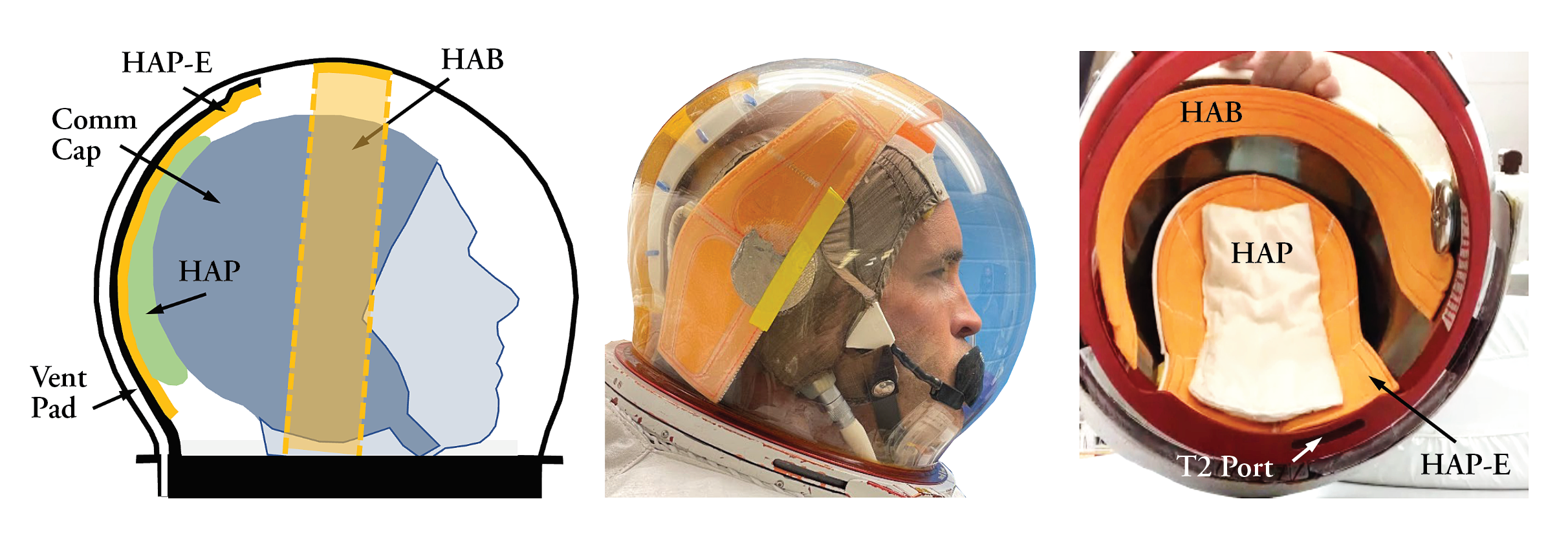
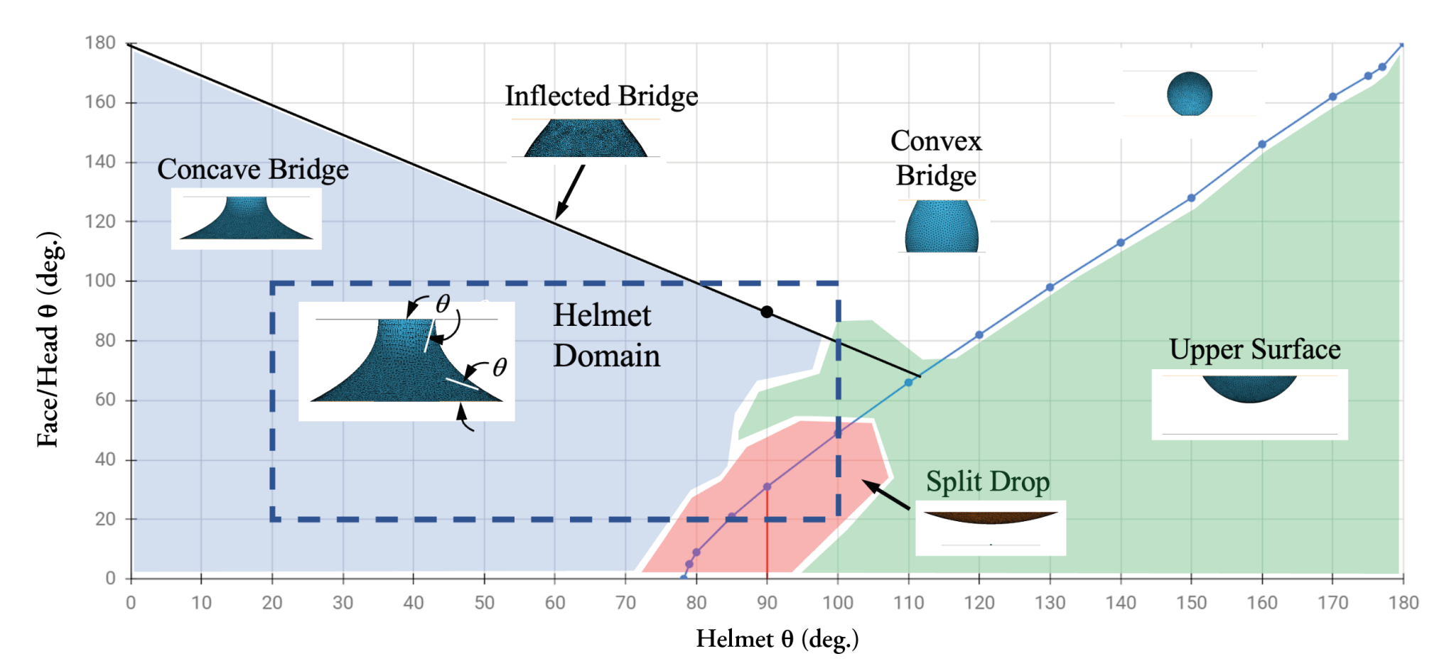
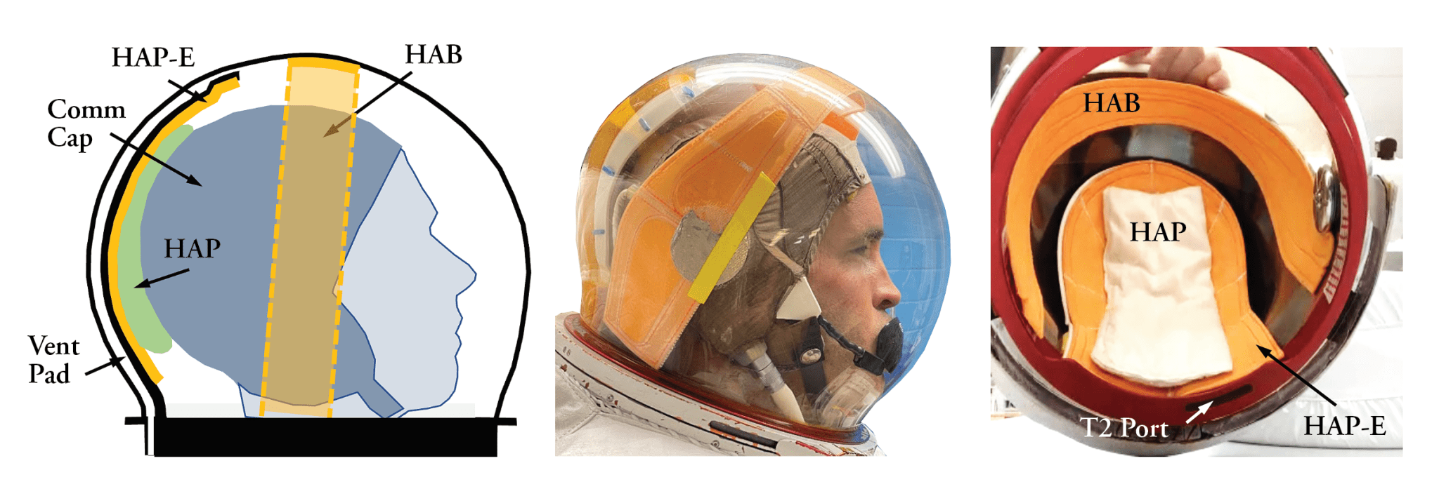
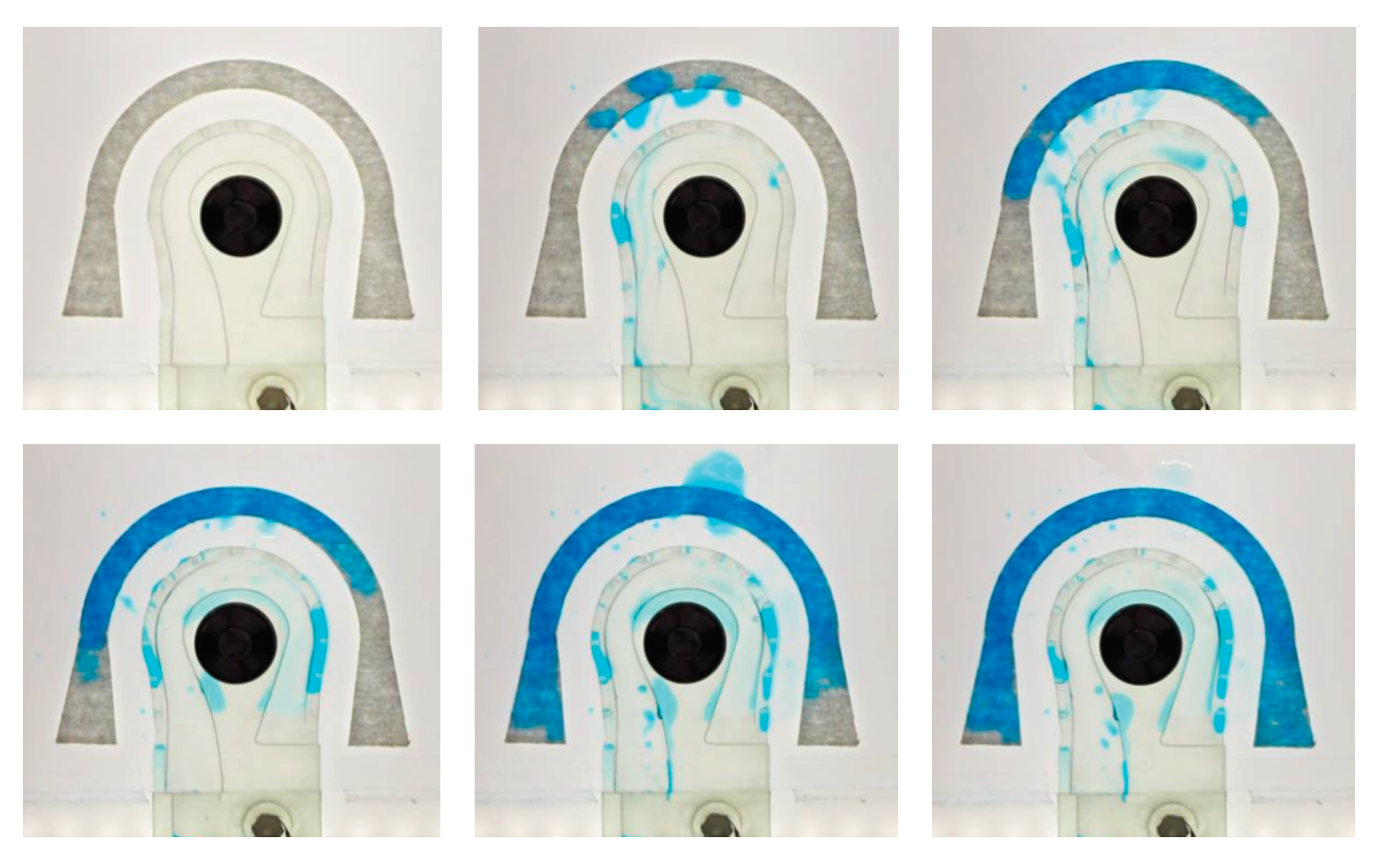
During EVA22 in 2013, water was observed in the helmet and assumed to be the result of a “burp” from the drink bag. No further investigation was pursued because water had been observed to some degree (water on visor, wet hair, etc.) on eight previous occasions. The result was a nearly catastrophic event during EVA23, where astronaut Luca Parmitano experienced dangerous quantities of water in his helmet. Both EVA23 and EVA35 in 2016 contributed to identification of drowning as a key risk, which resulted in several water mitigation approaches. Based on these approaches, the program determined the risk level to be acceptable for nominal EVA. However, in March 2022, a crewmember returning from EVA80 noticed water accumulated on the visor of his helmet obstructing ~30-50% of his field of view. Due to the increasing complexity of EVA objectives on EVA80 and forward, the ISS Program identified loss or reduction of visibility as a greater risk than previously recognized and sought to identify methods to prevent even small quantities of liquid water from forming in the helmet during EVA. The NESC was asked to provide support to the activity through modeling of the helmet and two-phase (water and oxygen) flow behavior in microgravity, through model validation testing, and through testing of mitigation hardware identified by the larger team. The model predictions provided a map (Figure 1) of anticipated liquid water formations based on the contact angle between the face or head and the helmet surface. Based on the ISS helmet with no water mitigations, the model predicted that large blobs would most likely form bridges between the helmet and face and that rupture of those bridges would result in the majority of liquid transferring to the face. To mitigate this risk, the ISS EVA80 team devised a solution to add absorbent materials in the path of the oxygen and water entering the helmet. Following EVA23, the helmet absorption pad (HAP) was added for bulk water collection. The improved mitigation strategy based on EVA80 included a HAP extender (HAP-E) and a helmet absorption band (HAB) (Figure 2). The NESC provided modeling of the mitigation hardware and validation testing of the HAB configuration using flow conditions anticipated in ISS operation (Figure 3). The testing provided ground validation of the HAB performance. The HAB and HAP-E have both been implemented in flight.
Evaluation of Terrestrial Portable Fire Extinguishers for Microgravity Applications
The tragic fire of Apollo 1 has, of necessity, instilled in NASA an enduring respect for the risk of fire in spacecraft. As such, robust fire detection and response systems have been a cornerstone of NASA-designed vehicles. Portable fire extinguishers (PFE) are a fundamental fire response capability of spacecraft and both carbon dioxide and water-based PFEs have been used by NASA historically. However, terrestrial-based PFEs, particularly those using new halon-based suppressants, may provide improved capability beyond the NASA state-of-the-art. In 2023, the NESC sought to evaluate the effectiveness of commercial-off-the-shelf (COTS) PFEs in microgravity. The team developed an analytical model to predict the discharge rate of three terrestrial COTS PFEs containing CO2, HFC-227ea, and Novec 1230. The model considered the internal geometry of the PFEs, the material properties of the suppressants and their corresponding PFE tanks, and the effects of microgravity and in-flight perturbations. The results predicted that for PFE tanks containing dip tubes, like those for HFC-227ea and Novec 1230 where nitrogen gas is used as a pressurant, microgravity plays a significant role in the discharge performance due to two-phase flow. Figure 4 shows the various equilibrium configurations based on gravity and perturbations. As a comparison, the analysis predicts >80% discharge of the HFC-227ea in the COTS PFE within ~30 seconds with the remainder discharging over ~0.5-1 hours when discharged in a terrestrial fire (Figure 4A), while only 60-80% discharges in 30 seconds with the remainder discharging over 1-2 hours in microgravity (Figure 4C).
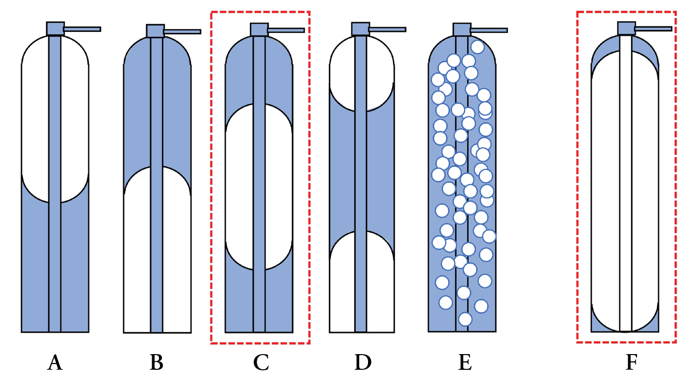
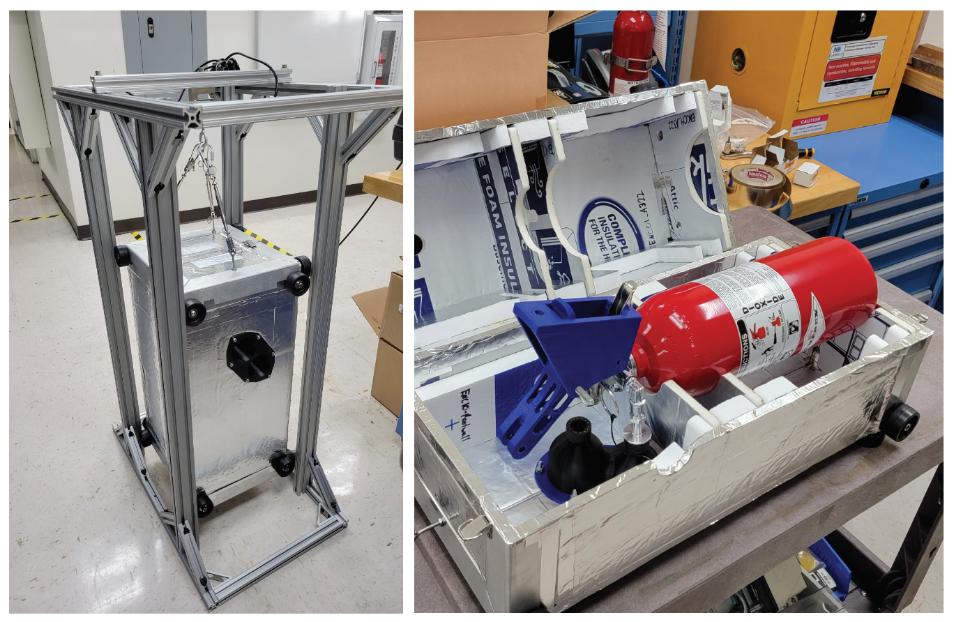
Based on this analysis, the use of terrestrially designed PFEs containing gaseous pressurant over a liquid suppressant will likely result in decreased initial discharge of the suppressant and significantly longer total discharge times in microgravity as compared to terrestrial discharge performance. Testing is ongoing to validate the models using a custom-designed PFE test stand (Figures 5 and 6) that enables multi-configuration testing of COTS PFEs.
Standardized Abrasion, Cut, and Thermal Testing for Spacesuit Gloves and Materials
State-of-the-art spacesuit gloves have been optimized for the challenges of ISS. Artemis missions call for high-frequency EVAs at the lunar south pole, where temperatures in the permanently shadowed region (PSR) will expose crew gloves to temperatures lower than ever previously experienced and where frequent and repeated exposure to regolith dust and rocks will present significantly increased risk for abrasion and cuts. With the development of new spacesuits by commercial partners, inexpensive and repeatable test methods are needed to characterize, evaluate, and compare gloves and glove materials for their thermal performance at PSR temperatures and for their resistance to lunar regolith abrasion and cuts. To address these needs, the NESC is leading a team to develop standardized test methods in coordination with ASTM International Committee F47 on Commercial Spaceflight.
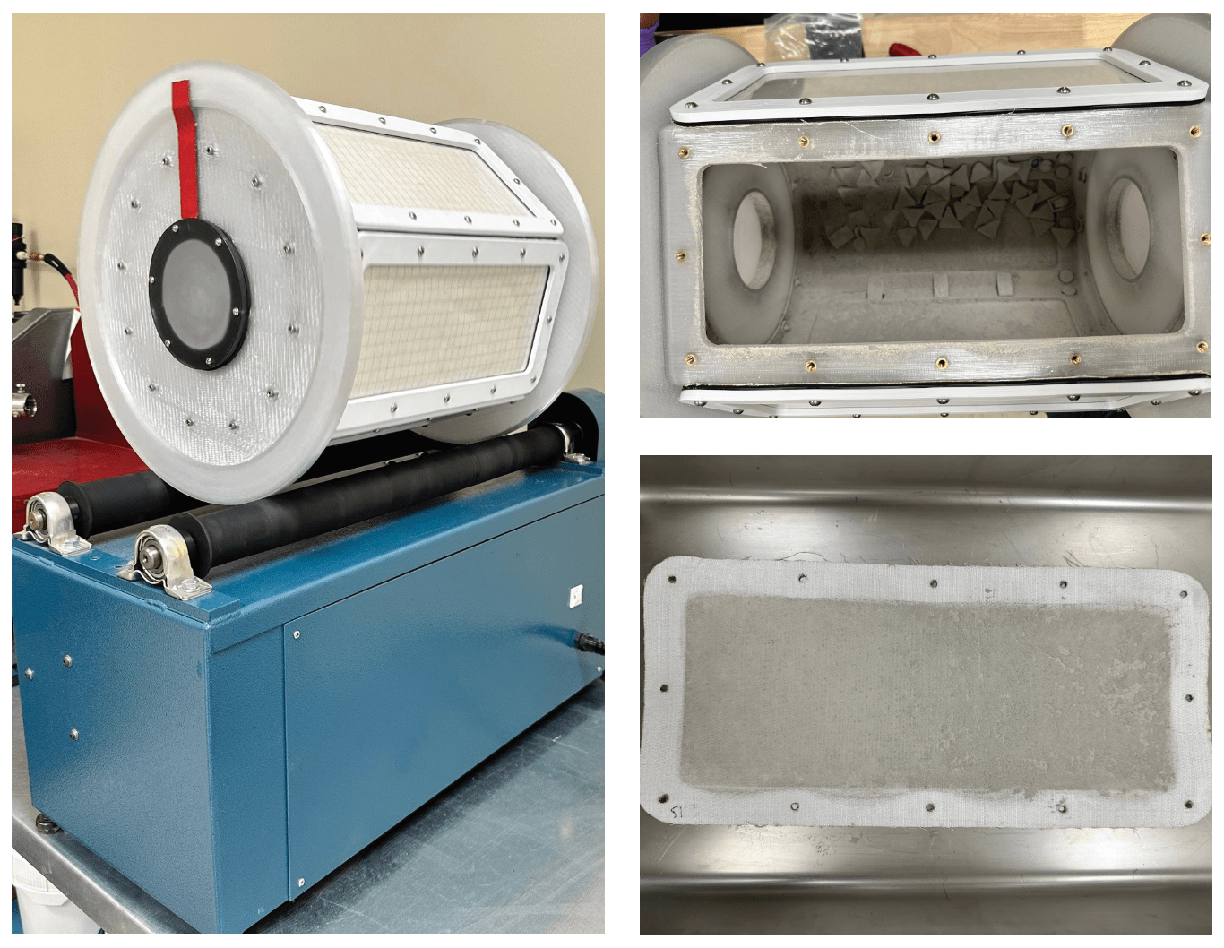
Three standardized methods are currently in development. The first method seeks to standardize lunar dust abrasion testing of glove (and suit) materials based on adapted “tumble testing” first proposed at NASA in 1990. The NASA-designed tumbler (Figure 7) enables testing of six samples per run and compares pre- and post-tumbled tensile strength of materials to compare abrasion resistance. The method is highly controlled using a commercially available tumble medium and lunar regolith simulant.
Because material properties change with temperature, the second method seeks to develop a standardized approach to evaluate the cut resistance of glove materials at relevant cryogenic temperatures. The method is an adaptation of ASTM F2992 Standard Test Method for Measuring Cut Resistance of Materials Used in Protective Clothing with Tomodynamometer (TDM-100) Test Equipment. In order to allow for cut evaluation at cryogenic temperatures, the TDM-100 cut fixture was modified to include channels for liquid nitrogen flow (Figure 8A), thereby cooling the test material to 77 K.
The third method seeks to evaluate the thermal performance of gloves down to PSR requirement temperature of 48 K. Historical thermal testing of gloves was conducted with human-in-the-loop (HITL) testing for both radiative and conductive cooling. Conductive cooling was accomplished by having the test subject grab thermally controlled “grasp objects” and maintain contact until their skin temperature reached 283 K (50 ºF) or until they felt sufficient discomfort to end the test themselves. While HITL testing is critical for final certification of gloves, iterative design and development testing would benefit from a faster, less expensive test. To meet this need, the NESC is developing a glove thermal test that uses a custom manikin hand designed by Thermetrics, LLC (Figure 8B).
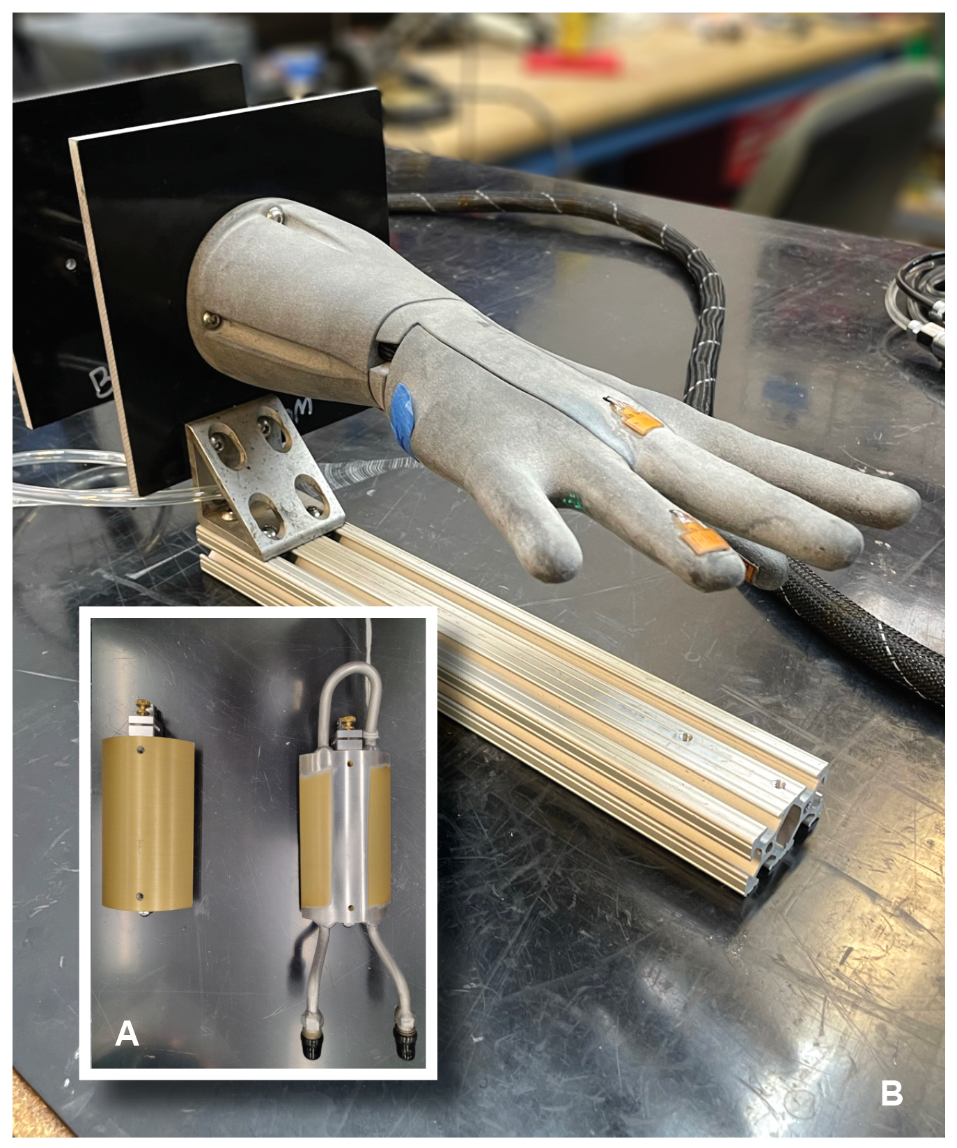
The manikin hand is outfitted with temperature and heat flux sensors to monitor heat transfer to the hand. The hand is placed within a spacesuit glove and thermally controlled with internal water flow to simulate human heat generation. The Cryogenic Ice Transfer, Acquisition, Development, and Excavation Laboratory (CITADEL) chamber at JPL is then used to test the glove thermal performance at a range of temperatures from 200 K down to 48 K. Thermal performance is evaluated to mimic historical HITL testing under both radiative and conductive cooling. Conductive cooling is accomplished through a temperature-controlled touch object and is evaluated using two touch pressures. All three methods will be incorporated as ASTM F47 standard test procedures following NASA and ASTM committee review and approvals (targeting 2024).
What's Your Reaction?








.jpg?#)


